


PLASTIC INJECTION MOULD TOOL
The mould tool is the key component in the injection moulding of plastic:
- It provides a passageway for molten plastic to travel from the injection cylinder (barrel) to the mould cavity.
- It allows the air which would be trapped inside when the mould closes to escape. If the air could not escape (be vented) then the moulded component would contain voids (air bubbles) and have a poor surface finish.
- It cools the moulding until it sets. The temperature of the mould is controlled because it is important that the moulding cools at the correct rate to avoid distortion and stress. In most systems water circulates through channels drilled through the mould, similar to a car engine cooling system.
- By means of ejectors the finished moulding is pushed from the mould.
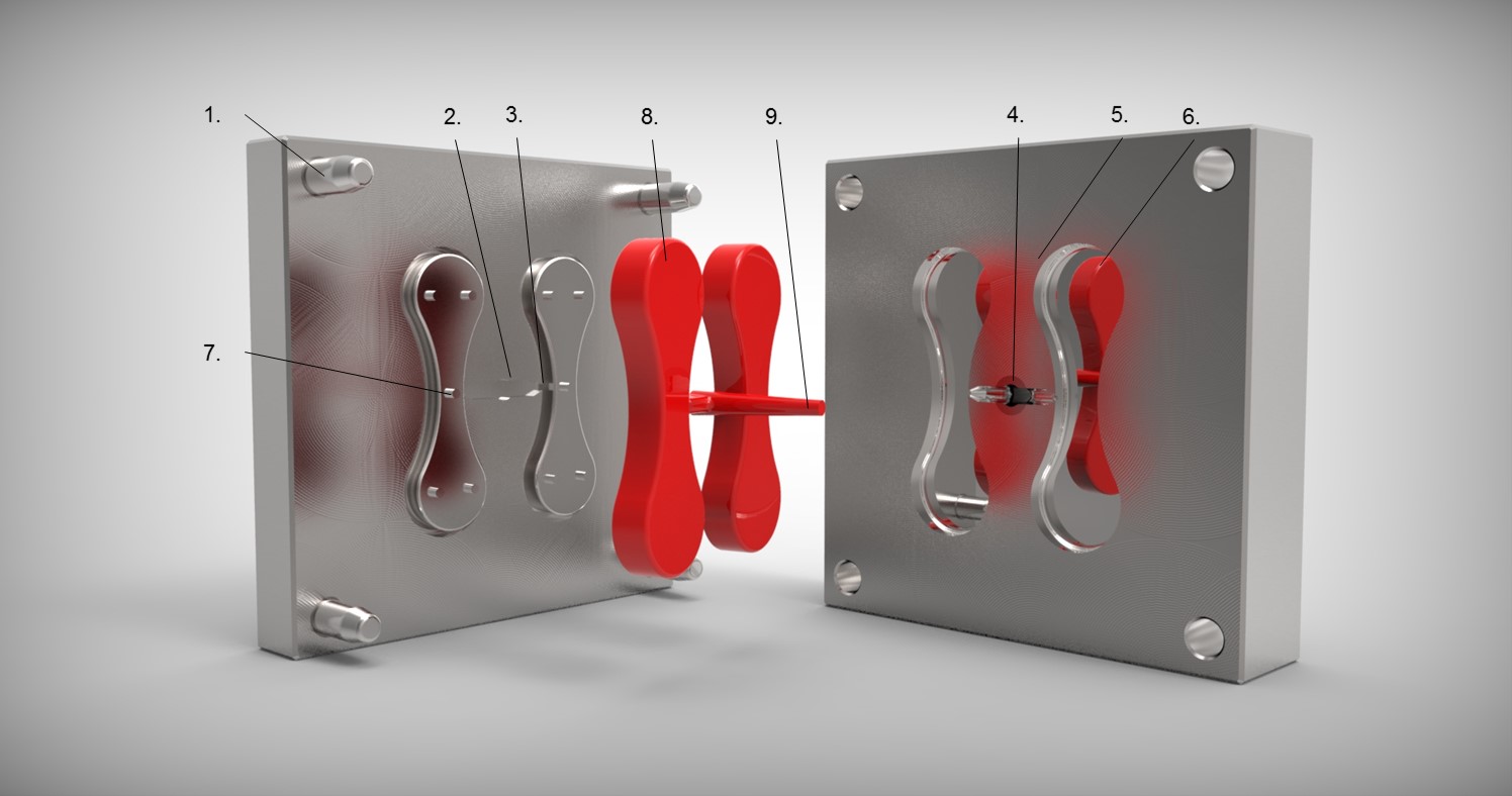
MOULD TOOL EXPLAINED
- Guide Pins – fixed to one half of the mould and align the two halves by entering the holes in the other half.
- Runner – passageways in the mould connecting the cavities to the sprue bush.
- Gate – Frequently the runner narrows as it enters the mould cavity. This is called a gate and produces a weak point enabling the moulding to be easily broken or cut from the runner.
- Sprue Bush – Tapered hole in the centre of the mould into which the molten plastic is first injected.
- Locating Ring – Positions the mould on the fixed platen so that the injection nozzle lines up with the sprue bush.
- Mould Cavity – The space in the mould shaped to produce the finished component(s).
- Ejector Pins – These pins push the moulding and sprue/runner out of the mould.
- The Shot – Total amount of plastic injected into mould.
- Sprue – Material which sets in the sprue bush.
")
")
")
")
